WT1 vs WT3 configurations and radiation loading analysis
- Elena Karpovich

- Oct 17, 2023
- 4 min read
On October 9th, we gave a talk at the Fourteenth Moscow Solar System Symposium held at the Space Research Institute. We were received warmly, and I enjoyed answering interesting and meaningful questions.
Our talk was devoted to two LEMFEV configurations, WT1 (wing-tail electric) and WT3 (wing-tail rocket engine), and the radiation loading they would be exposed to during their journey to Mars and on Mars.
The detailed analysis of our work will be published in the near future, and here I just give you a flavor of what we have discovered.
WT1 vs WT3 configurations
Both configurations, being wing-tail, will only fly once on Mars, and if equipped with a device to perform a single controlled vertical landing, they will also serve as a lander, measuring parameters of interest on the planet’s surface. A generic descent program and a flight profile of the WT (both 1 and 3) configuration are shown in Figure 1. The bottom left corner of Figure 1 presents the flight profile of an electric convertible boxwing BW1 configuration (which is not discussed here).

Figure 1. A generic descent program and flight profiles of the WT and BW LEMFEV configurations
Out of the scientific targets for a Martian probe, for an airplane, the walls of canyons and craters can be considered, for the following reasons:
- the relatively high atmospheric pressure expected below the topographical datum (which would allow reducing the airplane’s cruise speed and exploring the hypothesis of the water persisting in a liquid state deep inside craters);
- the high scientific significance of analyzing the inner sides of the crater rim; walls of craters and canyons might unveil millions of years of Mars’s history.
Another target for exploration may be the Martian boundary layer. The direct observational measurements within the Martian boundary layer remain relatively sparse, with the vast majority of in situ measurements on Mars having been obtained at altitudes a little higher than 1 m.
To establish the measures of merit for the design and evaluation of the LEMFEV configurations, we constructed a House of quality chart, or the Functional Quality Deployment Matrix.
The customer's, that is, the scientists', requirements, including reliability, payload mass, range, speed, and endurance, as well as the power available for instruments and the allowable mass of the data transmission system, were converted into aircraft parameters and properties. We concluded that in order to bring the maximum value to Mars exploration, the Martian airplane needs a power system that would feature the maximum possible operational time at the given payload mass. The operational time may be extended either by ensuring the overnight flight of a solar single-flight airplane or by providing a solar rechargeable airplane with a vertical take-off capability.
The optimum wing loading and thrust loading for the WT1 and WT3 configurations were defined using a constraint diagram, as exemplified in Figure 2.
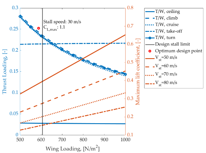
Figure 2. WT1 and WT3 Constraint Diagram: Aspect Ratio 3, payload 7 kg, stall speed 52 m/s, maximum lift coefficient 1.3
The optimal design point permits establishing the wing and thrust loadings at which all the requirements are met. For our airplane, at the design stall limit of 52 m/s, the maximum allowable wing loading is approximately 25 N/m^2, and the design thrust loading is 0.24. The iterative solution of the unity equation yielded the optimized value of the airplane’s gross mass, hence the design wing area and thrust.
For WT1, we selected Li-S batteries with a specific energy of 500 Wh/kg. Figure 3 shows the energy balance profile for the WT1 configuration.

Figure 3. WT1 configuration. Cruise energy balance profile: aspect ratio 3, altitude 1000 m,
Re 1.18e+05, Cl 0.85
The excess electrical power refers to the power available for charging the battery. Under the estimated conditions, the UAV’s battery can be charged during the day, so an overnight flight is possible.
In order to explore the design space available for the WT1 and WT2 configurations and compare them, a series of trade studies were conducted.
Within the adopted design space, the WT3 engine operating time (which is a function of the fuel tank length) varies between 6 and 17 minutes, with the gross mass being 45 – 105 kg and the wing span being 4.5 – 6.7 m. In the selected operating region, the WT1 configuration is optimized to be capable of a continued day-night flight; its gross mass is 34 - 65 kg, and its wing span varies from 3.9 to 5.4 m. As expected, the wing aspect ratio significantly affects the airplane gross mass.
The power plant mass is the greatest mass contribution to the WT3 configuration, despite its extremely low wing loading and a relatively high airframe mass ratio.
Radiation loading analysis
During delivery to Mars, the airplane will be exposed to external and internal radiation loading.
The external loading is due to the galactic and solar cosmic rays, while the internal radiation comes from the radioisotope heat sources (RIT) on board the descend module.
External radiation conditions were simulated using the dynamic GCL model and the probabilistic SCL model, modified to take into account the radial dependence of SCL fluxes as the spacecraft moves away from the Sun.
The analysis showed that if the thickness of the carbon fiber shell was about 2 mm, then the local absorbed dose for 259 days of flight would be 338 rad.
The local absorbed dose for the UAV's instruments from the RIT (internal radiation source) depends on the location of the device on the aircraft, its shielding by other devices and structural elements.
For a typical distance of 800 mm between the RIT and the UAV's devices, the dose will amount to 6 rad. For a distance of 100 mm between the RIT and the UAV's devices, the dose will rise to 380 rad.
When considering the operation of the UAV on Mars, we assumed an active operation period equal to 1100 days. The analysis revealed that the absorbed dose during the operation of the UAV in the atmosphere and on the surface of Mars would amount to about 14 rad (Si).
In addition, we estimated the saturation cross section and the threshold of the linear energy transfer effect for our UAV, for hard and soft failures, which turned out to be typical for electrical and radio devices with low fault tolerance.
The probability of failure-free operation of such a device for 1100 days will be 0.992. The number of failures during an extreme solar event will be ~ 1 failure in two days.
Finally, Figures 4-7 show the WT1 and WT3 folded and unfolded configurations.

Figure 4. WT1 vs WT3 configurations. Top view

Figure 5. WT1 vs WT3 configurations. Side view

Figure 6. Folded WT1 configuration inside an aeroshell

Figure 7. Folded WT3 configuration inside an aeroshell


Comments